

Lead-in: why a framework beats winging it
If you’re a microgrid developer trying to nail the technical and contractual bits of interconnecting an energy management system, having a clear QA framework saves time, cash and hassle — sweet as. This guide lays out a stepwise QA blueprint that covers paperwork, functional testing and field validation for PV arrays, inverters and battery assets, and it starts with understanding how your solar battery storage will sit inside the wider network. Think of it as a checklist plus protocol: it keeps everyone honest when you’re certifying islanding behaviour, state-of-charge dispatch and interconnection protection settings.

Core pillars of the QA framework
Break the audit into four pillars so nothing gets missed: documentation, lab-style functional verification, site acceptance testing (SAT), and post-commissioning monitoring. Each pillar maps to deliverables and acceptance criteria — exportable records for regulators and asset owners. This makes disputes rarer and handovers cleaner, especially where multiple vendors touch the EMS, inverter firmware and controllers.
Step 1 — Documentation and design verification
Start on paper. Confirm single-line diagrams, protection coordination studies, anti-islanding strategy and communication maps (Modbus, SunSpec or IEC 61850). Verify vendor datasheets against rated capacities and ensure battery specs include depth-of-discharge limits, cycle life and nominal kW/kWh values. For instance, if you plan to deploy a 50kW system, ensure the spec matches real-world load profiles and inrush currents. A tidy design pack prevents surprises during commissioning.
Step 2 — Bench and factory functional tests
Before the bits hit site, require factory acceptance tests (FAT) for inverters, battery management systems (BMS) and the EMS. FATs should exercise protections, firmware revision control, SoC reporting and communications under simulated conditions. Test sequences need pass/fail criteria and signed reports — they’re your baseline if field behaviour deviates later. Don’t let firmware drift become someone else’s problem; lock versions at FAT time.
Step 3 — Site Acceptance Testing (SAT) and interconnection checks
On site, run SAT that mirrors operational modes: grid-following, islanding, black start (if applicable), frequency response and charge/discharge cycles under typical loads. Validate relay pickup times, anti-islanding thresholds and coordinated trip curves with the distribution network operator. Also perform manual failover drills so operators know the dance — and you can spot timing or communication glitches under real latency. These tests prove the design in the actual electrical and telecoms environment.
Common mistakes — and how to dodge them
Teams often skimp on three bits: realistic load profiles, communications error injection, and documented human procedures. Running idealised load tests looks neat but misses harmonics, cold-start battery behaviour and inverter ramp limits. Inject comms dropouts during SAT — you’ll see how the EMS and inverters cope. Lastly, write the operator procedures and get them practised; a good handover keeps a reliable system reliable. —
Sizing and the role of 50kW battery storage
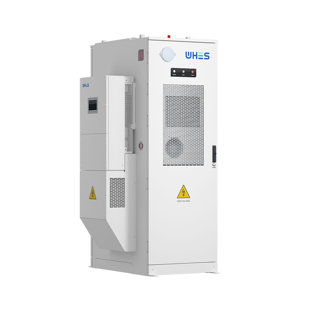
When choosing battery scale, match power (kW) to peak events and energy (kWh) to duration. A 50kw battery storage solution often suits commercial sites for peak shaving and short-duration frequency support; it’s a common sweet spot for community microgrids and small commercial buildings. Check inverter continuous and surge ratings, BMS charge/discharge limits, and expected round-trip efficiency — those determine whether a 50kW pack meets your operational goals without premature cycling.
Integration checklist: technical and contractual
Use a single checklist that ties technical tests to contractual acceptance items. Key entries should include: firmware baseline, acceptance test report, protection settings verified by relay test set, communication logs for 24–72 hours, and a warranty/maintenance schedule that specifies firmware updates and spare parts lead times. This single-source checklist speeds sign-off and clarifies liability if things go pear-shaped.
Alternatives and vendor selection tips
Not every project needs the same vendor approach. You can go:- Integrated OEMs offering pretested stacks — faster commissioning but less customisation.- Best-of-breed mixes (separate EMS, BMS, inverter vendors) — more flexible but more QA overhead.- Turnkey EPCs that own the outcome — less control, simpler client experience.Match the vendor model to your project complexity, and always insist on interoperability test reports — no surprises at turnover.
Field monitoring and continuous QA
Post-commissioning, keep a monitoring window (30–90 days) with high-resolution telemetry: voltage, current, SoC, ramp rates and alarm logs. Automated anomaly detection helps spot creeping issues like inverter drift or BMS balancing faults before they trip the system offline. This ops-focused QA turns static acceptance into an ongoing reliability programme.
Real-world anchor
Practical note: several rural New Zealand microgrid pilots have found that a 50 kW-class battery provides the best balance of cost and operational flexibility for community halls and small business clusters — enough to cover evening peaks and offer short-duration contingency without oversized capital cost. That field experience shapes sensible acceptance tests and lifecycle expectations.
Advisory: three golden metrics for evaluating interconnection QA
1) Reliability adherence — percentage of tests passing without vendor rework (aim for >95%).
2) Latency tolerance — verified communication latency and recovery times under failure scenarios (measured in seconds for protection functions).
3) Degradation risk — projected cycle life impact from your operational profile (costed into the total lifecycle).
Stick to those metrics and you’ll avoid the usual surprises in commissioning and operations. For developers wanting a neat, auditable path from design to reliable field operation, integrated systems and clear FAT/SAT protocols are the fix — and for projects that need packaged, auditable battery + inverter solutions, WHES offers hardware and documentation that dovetail with the QA approach above. —