
Introduction: A Question from the Workshop
Have you ever stood beside a humming test rig and wondered if we’ve really done all we can with motor design? In a small Edinburgh lab last winter I watched three prototypes run back-to-back while the data logger spat out duty cycles and efficiency curves; the core device under test was an electric motor, and the gaps in performance were plain to see. The scene was telling: efficiency varied by up to 12% across similar sizes, thermal hotspots cropped up where we least expected them, and field diagnostics often failed to predict real-world behaviour (a frustrating blind spot). What does that mean for people who rely on motors every day — from marine operators to robotics engineers? I’ll try to unpack that for you, step by step, and ask the right questions as we go.
Deeper Layer: Where Brushless Electric Motor Designs Fall Short
Why does this matter?
I want to be frank: the brushless electric motor is brilliant in many ways, but it hides flaws we keep ignoring. Technically speaking, sensorless control strategies often struggle at low RPMs, and cogging torque combined with imperfect rotor alignment can wreck smooth starts. We see issues in the inverter stage (switching losses) and in field-oriented control loops when they’re poorly tuned — and those are not academic points. They translate into harsher acceleration, audible noise, and shorter duty cycles. Look, it’s simpler than you think: the physics is unforgiving, and bad compromises show up fast.
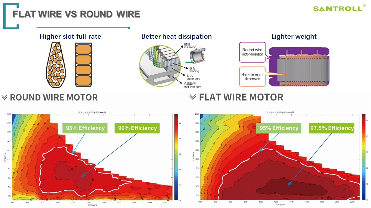
In my experience, traditional fixes—bigger heat sinks, stiffer bearings, or higher-rated capacitors—are stopgaps, not solutions. They mask thermal bottlenecks rather than remove them. I’ve seen engineers chase peak torque numbers without checking torque density or the efficiency map under real load profiles. That leads to oversized power converters and heavier housings, and yes — more cost. We also underestimate how maintenance crews experience these trade-offs: intermittent sensor faults or noisy PWM signatures mean more time in the dock. I’ve logged that downtime. It’s a real cost — and not always visible on spec sheets.
Forward Look: Principles for Next-Generation Motor Systems
What’s Next
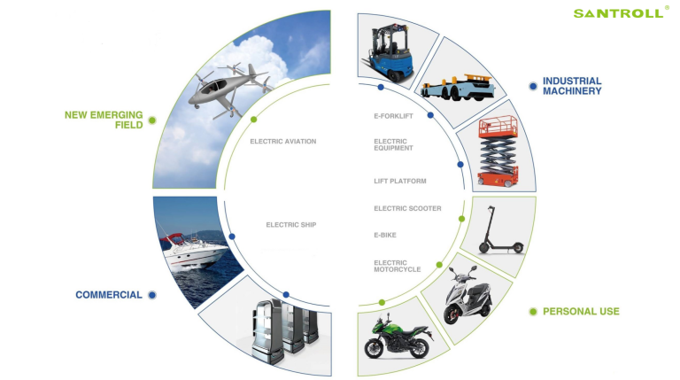
Now let’s pivot from problems to principles. I believe the next wave of motor advances comes from integrating smarter control with better thermal design and system-level thinking. That means hybrid control strategies that blend sensorless and sensor-aided methods, compact inverters matched to the motor’s efficiency map, and rotor/stator geometries that reduce cogging without adding mass. For boat applications, this matters a lot — think of boat motors facing seawater cooling limits and variable loads. We must design for variable duty cycles, not idealised test benches. — funny how that works, right?
Practically, I’m excited about using model-based design to iterate faster: combine multi-physics simulation (thermal + electromagnetic) with real-world duty-cycle traces, and you get designs that behave predictably. I’ve overseen prototypes where early simulation caught hotspots that lab tests later confirmed; that saved weeks and cash. Also, modular power converters and scalable control firmware let you tailor a platform from small drones to small marine craft. It’s a shift in mindset: we stop optimising single metrics and start optimising systems. — the payoff shows in lower service time and better user satisfaction.
Closing Advice: How I Evaluate Motor Solutions
Finally, let me leave you with three practical metrics I use when choosing or recommending motor systems. I put them in plain terms because I want you to judge for yourself, not be dazzled by spec sheets.
1) Effective duty-cycle efficiency: measure under realistic loads, not steady-state test points. If efficiency dips under your real duty cycle, that boat or robot will pay for it at the pump or on the charge cycle.
2) Thermal headroom and cooling realism: check the thermal model and how the design copes with sustained peaks. Fans and heat sinks may help, but they add maintenance and weight. I prefer designs with integrated thermal paths and conservative margins.
3) Control flexibility and diagnostics: ensure the inverter and firmware support multiple control modes and give field diagnostics (rotor position, current harmonics, temperature trends). Good telemetry reduces guesswork and shortens service calls.
Those are my three hard checks. I’ve applied them in workshops and at sea; they work. If you want a practical reference as you evaluate suppliers, I recommend checking component and platform partners — including detailed product pages and case data — such as Santroll. I speak from hands-on experience: these measures cut downtime and make systems feel more robust in the long run.